 Print
Print

Discovery Telecom
Communication & other equipment.
Easy to choose, easy to buy
Tel./Fax: +44 20 3769 1919
E-mail: info@discoverytelecom.eu
Communication & other equipment.
Easy to choose, easy to buy
E-mail: info@discoverytelecom.eu
Wideband amplifier for IMSI / IMEI / TMSI catcher
|
|
The main functions and characteristics
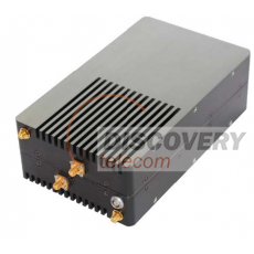
The Wideband Amplifier is a small (196 mm x 118 mm x 64 mm) dual RF front end that supports GSM/GPRS/EDGE, UMTS/HSPA/WCDMA, CDMA2000, and LTE-FDD/TDD capability varying from 700–950 MHz and 1.7–2.7 GHz.
This complete integrated RF front end is software-defined and offers frequency-agile, multi-standard RF capabilities, enough RF performance for small cell applications. The Wideband Amplifier is a portable fan-less enclosure housing two independent RF front end (RFE) cards and powered using an external battery.
It has a typical power consumption of 30W at 25°C ambient with both transmitters enabled.
The Wideband Amplifier has an on-board Environment Management IC (EMIC) to monitor and respond to physical parameters such as RF output power, receiver interference, and operating temperature.
Software control of the Wideband Amplifier is handled by OnBoard Management (OBM), available with OBM version 2.0.1 and later. The plugin will probe and instantiate two distinct RfFrontend software objects, one for each of the two RFE cards (Card A & Card B) in the unit.
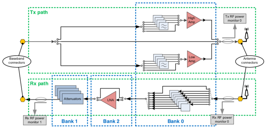
Each RFE card comprises 2 paths: a TX path and an RX path. The figure below illustrates how the RF paths are mapped and controlled by the OBM software: the TX path has only one bank controlling all components, while theRX path has 3 banks.

When OBM probes the Wideband Amplifier, paths on Card A are mapped to the baseband side’s antenna connector (0,0)and paths on Card B are mapped to baseband connector (1,0). Refer to the OBM documentation for details on how to use antenna connector IDs to interact with the RFE.
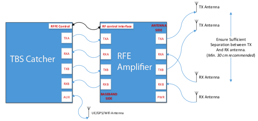
The figure below illustrates the connections between the Wideband Amplifier and the TBS-Catcher.

Ensure a minimum of 30 cm separation between the TX and RX antennas. Do not connect antennas
directly to the RF ports on the Wideband Amplifier. Attach antennas to the Wideband Amplifier using RF interconnection cables.
This page was printed from the website
www.discoverytelecom.eu
Please check prices and availability of equipment.
www.discoverytelecom.eu
Please check prices and availability of equipment.
